ECE 387 TI INA219
ECE 387 Midterm Project
Interfacing a Texas Instruments INA219 current / power sensor to an ATMEGA 328P microcontroller.
Project Completed for ECE 387 at Miami University, Spring 2022
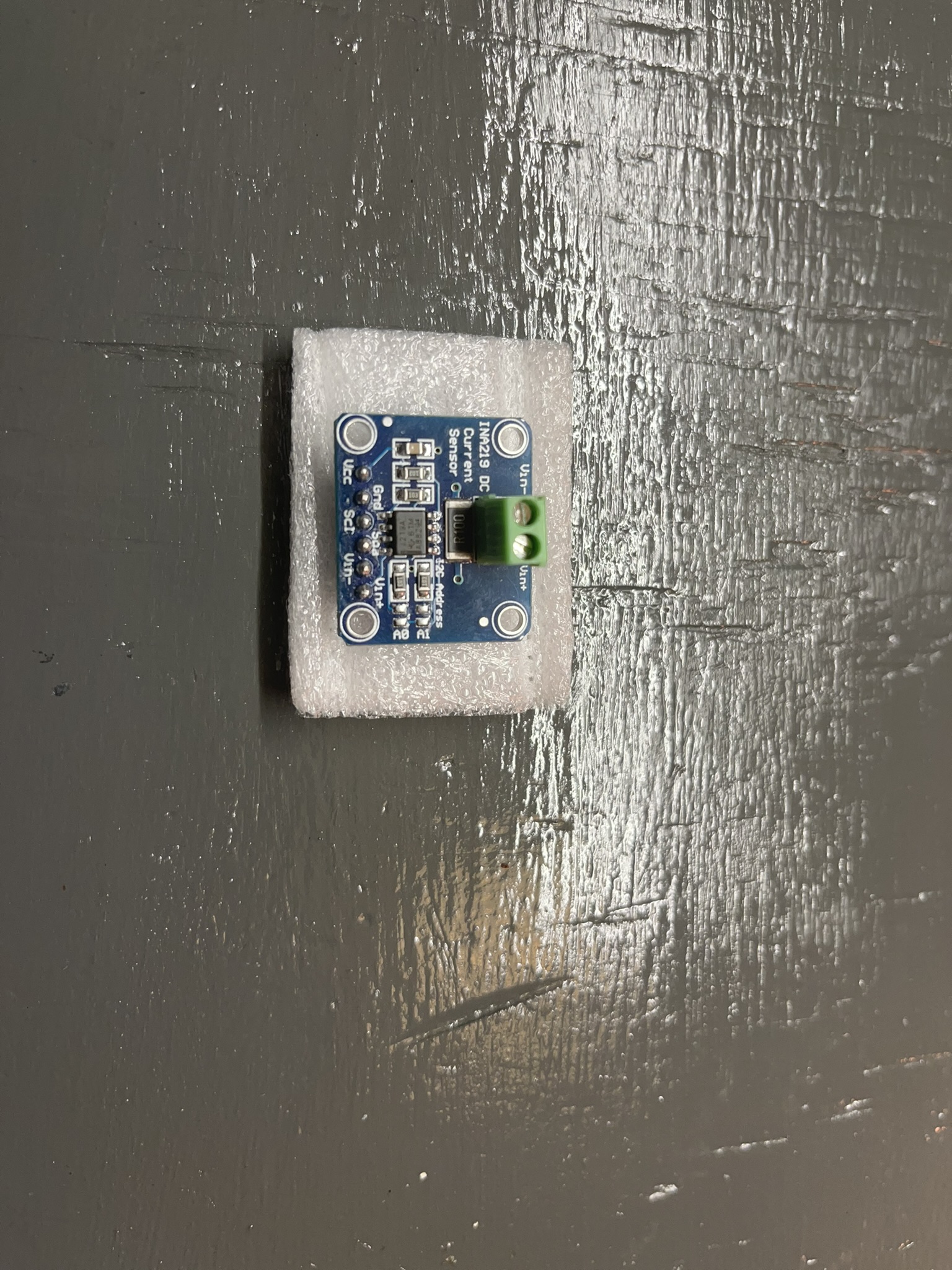
Texas Instruements INA219 DC current measurement chip on breakout board.
The breakout board I used for this project takes care of several details necessary for proper functionality.
- The first is the board contains a 0.1 ohm shunt resistor for the current measurement.
- The second are 10k ohm resistors on both the SDA and SCL lines of the I2C interface.
Arduino Wiring
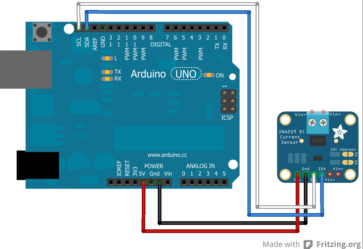
Wiring the INA 219 to an Arduino (or any microcontroller) is very trivial. It only requires two pins, the SCL and SDA as described above. Where possible, hardware Two wire serial interfaces should be used, if not practical, any digital pins can be used, however. It is also important to note that if a breakout board such as the one I used is not going to used, components such as the pullup resistors for the SCL and SDA resistors as well as shunt resistors will be necessary. Without using a breakout board it is also possible to use different values of shunt resistors to measure different ranges of power consumption, with different scales.
Arduino Demonstration Setup
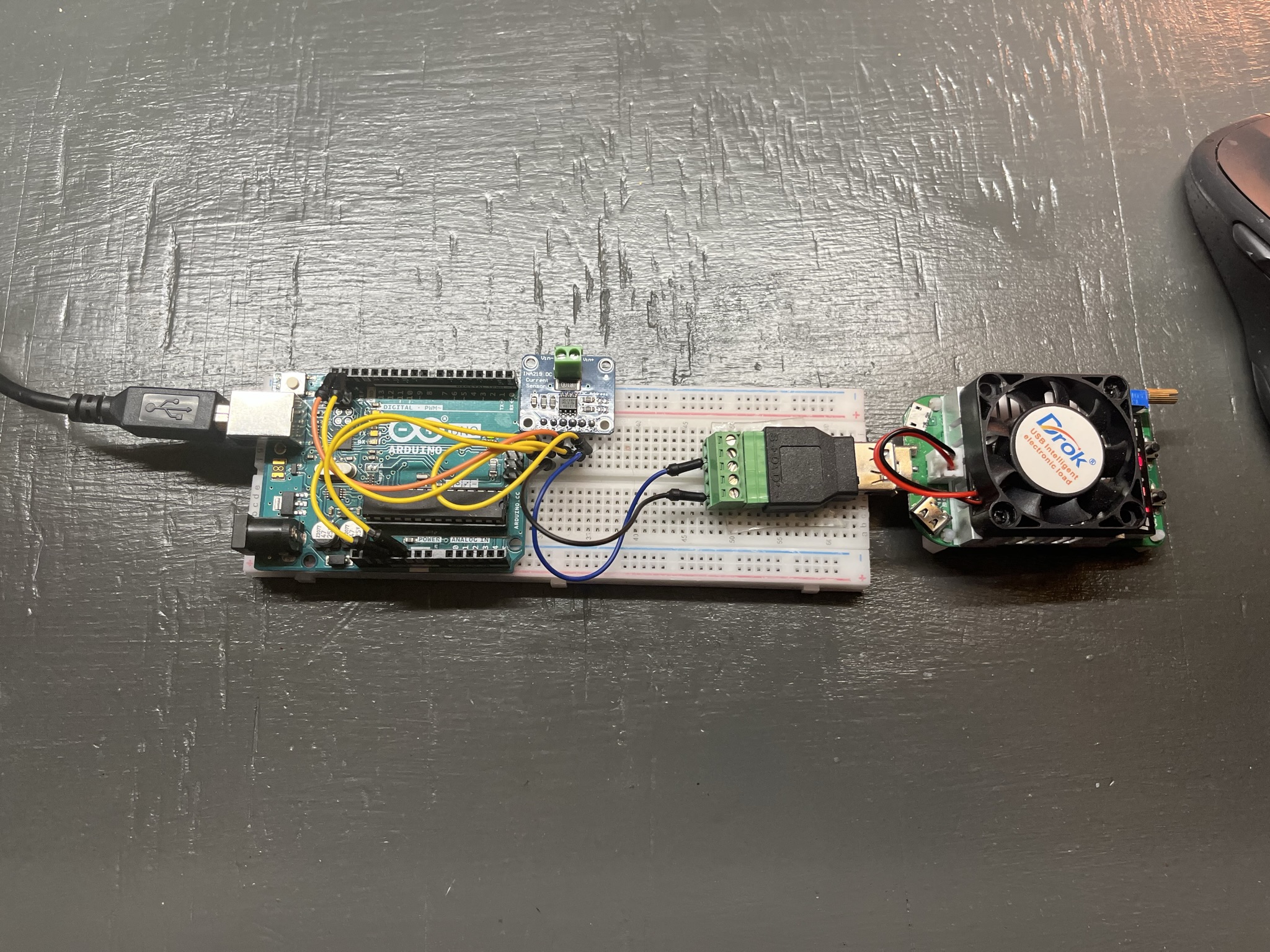
For this project I setup a simple test using the INA219 to measure the power consumption of a small USB Digital Load. The Digital Load allows changing the current it draws by turning a knob. It also prints out the voltage, current, and power it is consuming at any given time.
INA 219 Operation
The INA219 chip uses I2C communication to communicate with other devices (Arduino). I2C allows connecting many devices 128 devices (7-bit address, from 0-127) using only two pins, a clock signal and a data signal. This works by first transmitting a 7-bit address that the I2C bus and devices use to determine what device is being communicated with. An 8th bit is used as a read/write bit.
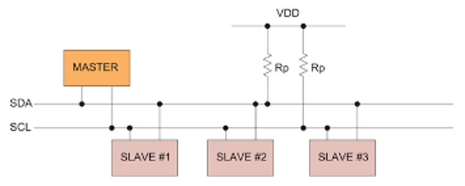
Shows Configuration of I2C
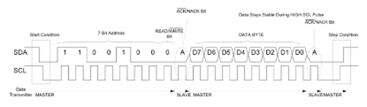
I2C Data Configuration
INA 219 Data Register Configuration
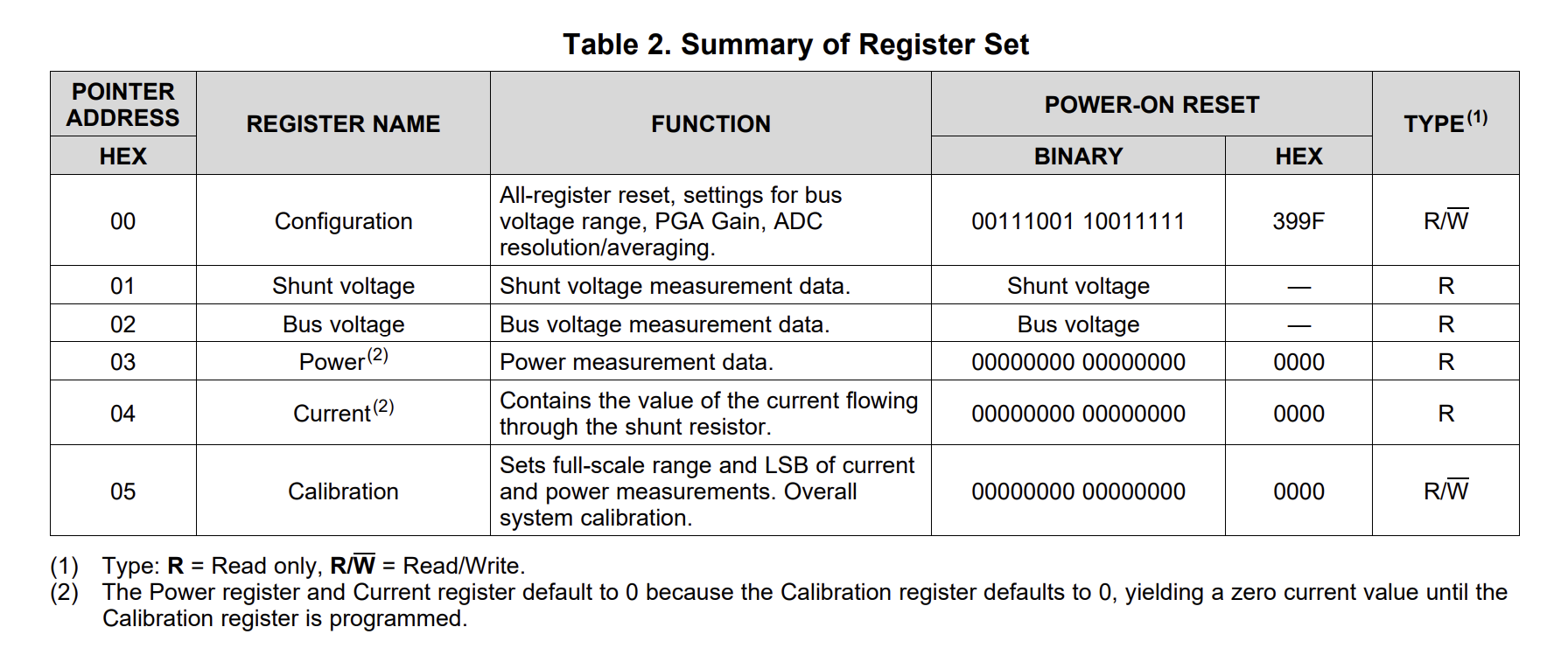
The INA 219 contains 6 different data registers as seen in the register table from the datasheet. The chip also contains a 7th data register, called the buffer pointer. The buffer pointer allows the programmer to write the pointer address for the register to be used next. Then, the next time the chip’s address is contacted with the read/write bit set to read, the device will return 8 bits of data stored in the register previously specified, most significant bit first. The registers all contain 16 bits of data, so to read the other half the address and read command must be sent again. For my demonstration, I then bit-shifted the data and combined it together to make a 16 bit integer. Some values must also be bit-shifted to remove unneccsary bits included in the raw data that do not carry any real value.
Configuration and Calibration
The configuration and calibration registers on the INA 219 can be used to have the INA 219 calculate the current and power values, so they can just be read out and directly used by the microcontroller, but they do need to be programmed. These registers are also volotile and must be reprogrammed each time the sensor is power cycled. I did not program these registers with my program, instead relying on the Arduino to complete these calculations.
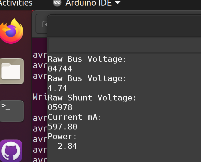
The only other task completed for this project was to print out the data to the Serial Monitor to be interpretted. This is using the USART library used by many of our other labs for ECE 387. The USART library does not include a method to print floating point numbers inside it, so I simply converted floating point numbers to Strings where necessary. I then used the USART library to print to the Serial monitor.

Video of Working Project
The program is being compiled and uploaded to the board using AVR-GCC and avrdude from command line using a python script. Therefore it uses a USART library given by my professor with unknown origins, and Peter Fleury’s Twimaster (Two-wire interface, master) to communicate with the INA 219 over I2C instead of the default arduino libraries.
You may notice that the current/power values seem to be slightly off between the readout on the digital load, and the sensor readings. This is largely for two reasons: The resistance of the breadboard and jumper cables decreasing the voltage that is being measured by the load, this was confirmed by using a multimeter. And secondly the inaccuracy of the inexpensive digital load.