ESP8266 RGB PCB
In September 2021 I used a solder breadboard to connect a ESP 8266 / NodeMCU microcotroller to a set of RGB LED’s. I connected these to Home assistant using ESPHome. These worked pretty well for controlling RGB lights, but were not very flexible or repeatable. I made two of these and each were vastly different although the underlying circuit was the same.
Project Files: Gitlab Repository
ECE 493 Final Project
In college I took a power electronics class (ECE 493 at Miami University with Dr. Mark Scott) where the final for the class was designing, assembling, and testing a IGBT switching cell on a custom PCB. ECE 493 Final Project This was my first look at designing PCB’s. We used Altium Designer, which has a very nice student version to design the board. We also had to order the boards from overseas fabricators, and assemble the many surface mount components on to the board. Although I have quite a bit of expierence soldering through-hole components, this project was the first that I soldered surface mount components or used a hot-air reflow station.
Custom PCB
As I am no longer a student I no longer qualify for the Altium Designer Student license. Autodesk Fusion 360 offers powerful hobbyist license’s that I am already using for designing my 3D printing. Fusion 360 also has a schematic designer, as well as a PCB design function. I used these to design the circuit and PCB layout for this project, although the export functionality provides less options than that of open-source KICAD, so I used KICAD for exporting the files requested by the board fabricator. Since this project, I have used KICAD for other projects from the beginning, including my lighthouse project.
The (messy) schematic diagram I created in Fusion 360. It is a simple circuit so I did not spend too much time keeping the layout clean.
I spent much more time creating the board layout for the PCB. I wanted this to be clean and well layed out.
I was happy with the boards when they arrived but noticed a few mistakes. The text for the resistor size is wrong (10K ohms instead of 1k ohms.) and some of the text sizes were to small to be easily readable. These will be fixed in a future design update. Initially I just ordered 5 from PCBWay. They were a little picky with file naming but I was impressed with the quality and price of the boards.
Assembly
I purchased a Hot Air reflow station to make placing the small surface mount components easier. The model I purchased was similar to what I had used in college for my power electronics project. I also 3D printed a Nozzle Holder to hold the different sized nozzles. A hot air reflow station pushes high-temperature air through different size nozzles to melt solder on specific areas of PCB’s. My technique for reflowing boards involves using lots of flux and tweezers in my other hand to slide the components into position.
Completed Boards
I was pretty happy with the final project. I did uncover a few improvements I could include in future designs including adding mounting holes and some test points.
Oscilloscope Testing
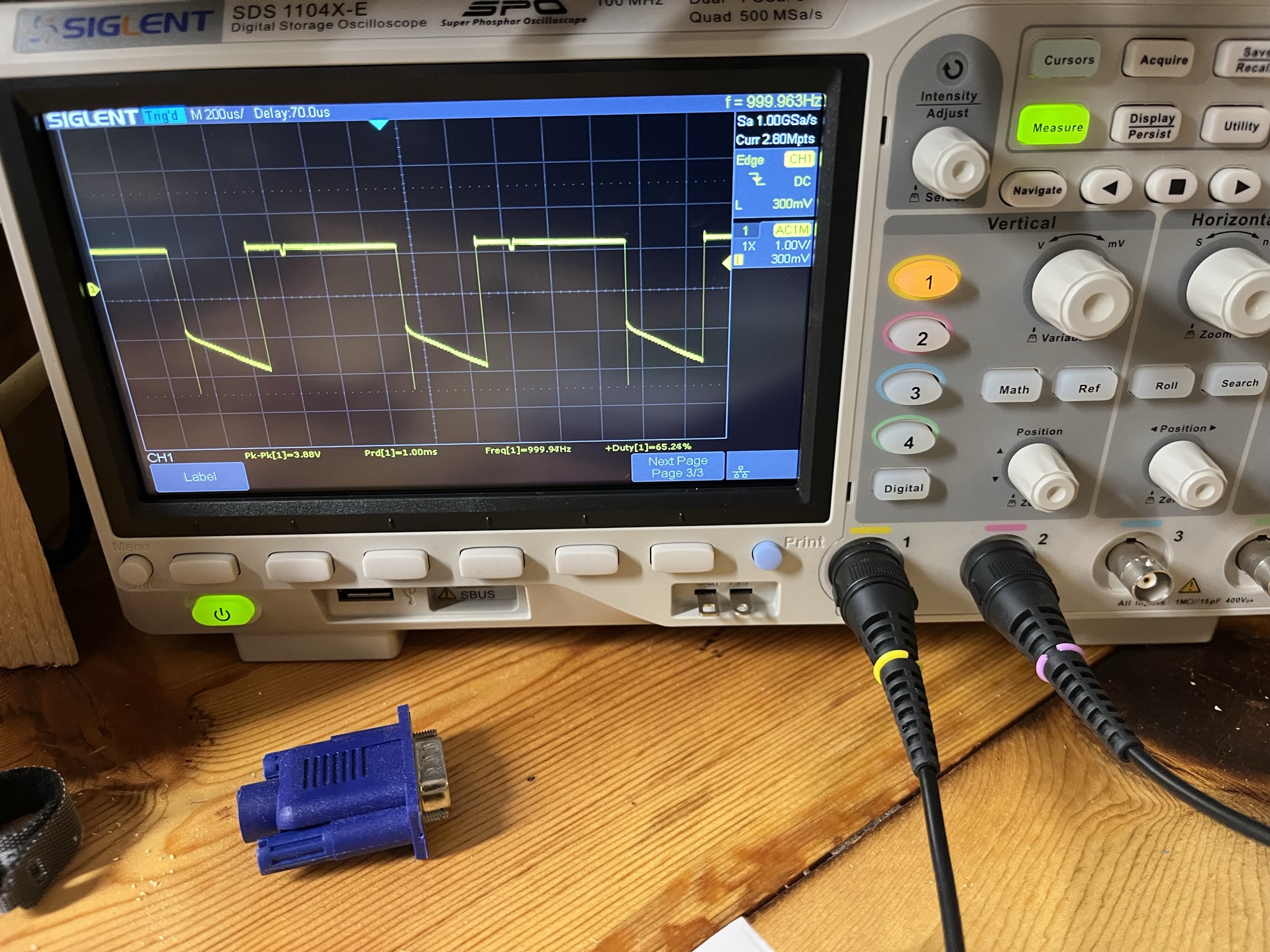
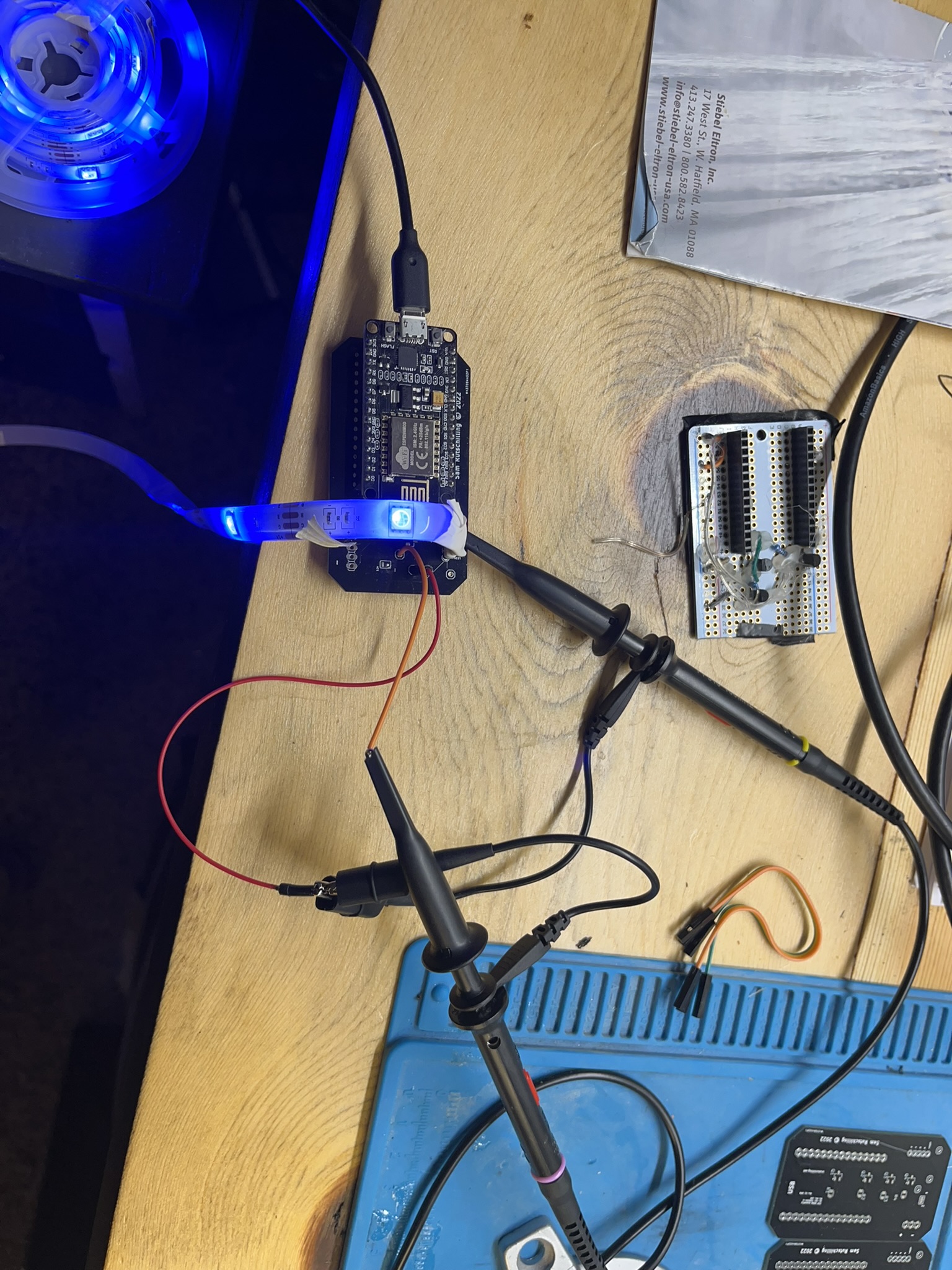
I connected my oscilloscope to the board just to see what the waveform would look like. It looked about as I expected.

