ECE 387 Toy Project
ECE 387 Individual Final Project
Overview
This useless box is entirely 3D printed and uses a Arduino Micro (ATMEGA 32U) programmed in C using AVR-GCC and AVRDUDE.
The operation of the Useless Box toy is very simple … there are two switches, and when each of them are turned on, an arm emerges from inside the box and turns it back off. Therefore the Useless Box serves no real function: it is “useless”.
Operational Demonstration

Operational Overview
The Useless box is a simple toy; it turns the switch off when it is turned on by a user.
3D Printed Parts
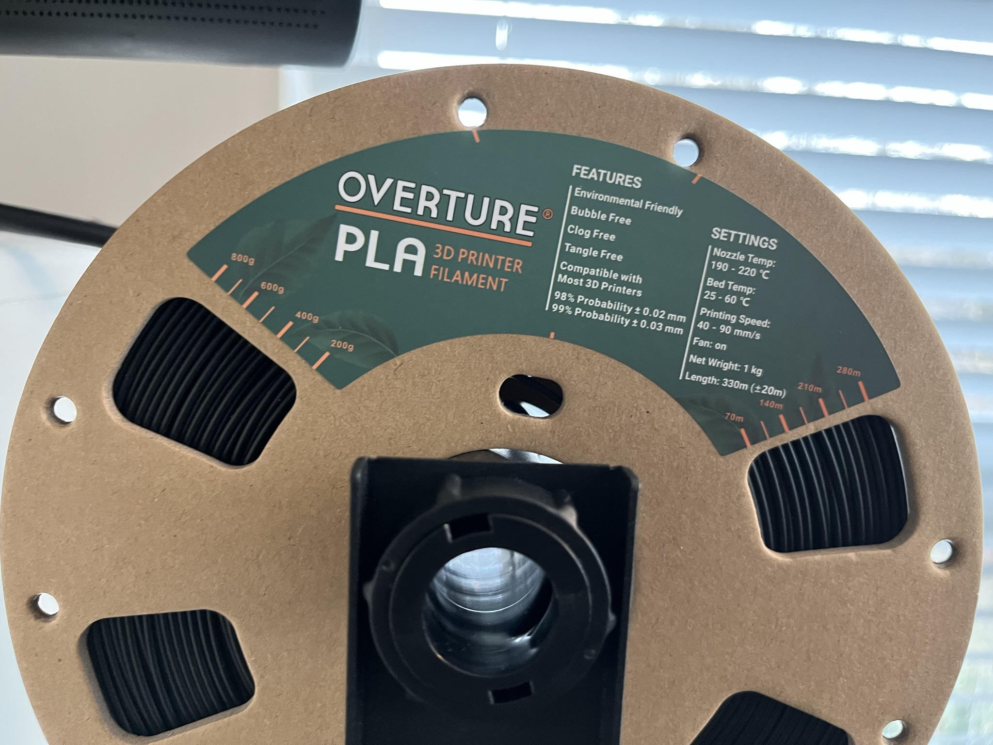
I designed all of the mechanical parts for the Useless Box in Autodesk Fusion 360. All of the design files are located in this Folder. Each part was “sliced” (split into layers and 3D printer gcode) using Utlimaker Cura. I then printed each of the pieces on my Creality Ender 3 V2 3D printer using PLA (polyactic acid) filament. Each piece is is hollow and includes between 40 and 60% fill in a triangular manner to reduce print time and increase strength.
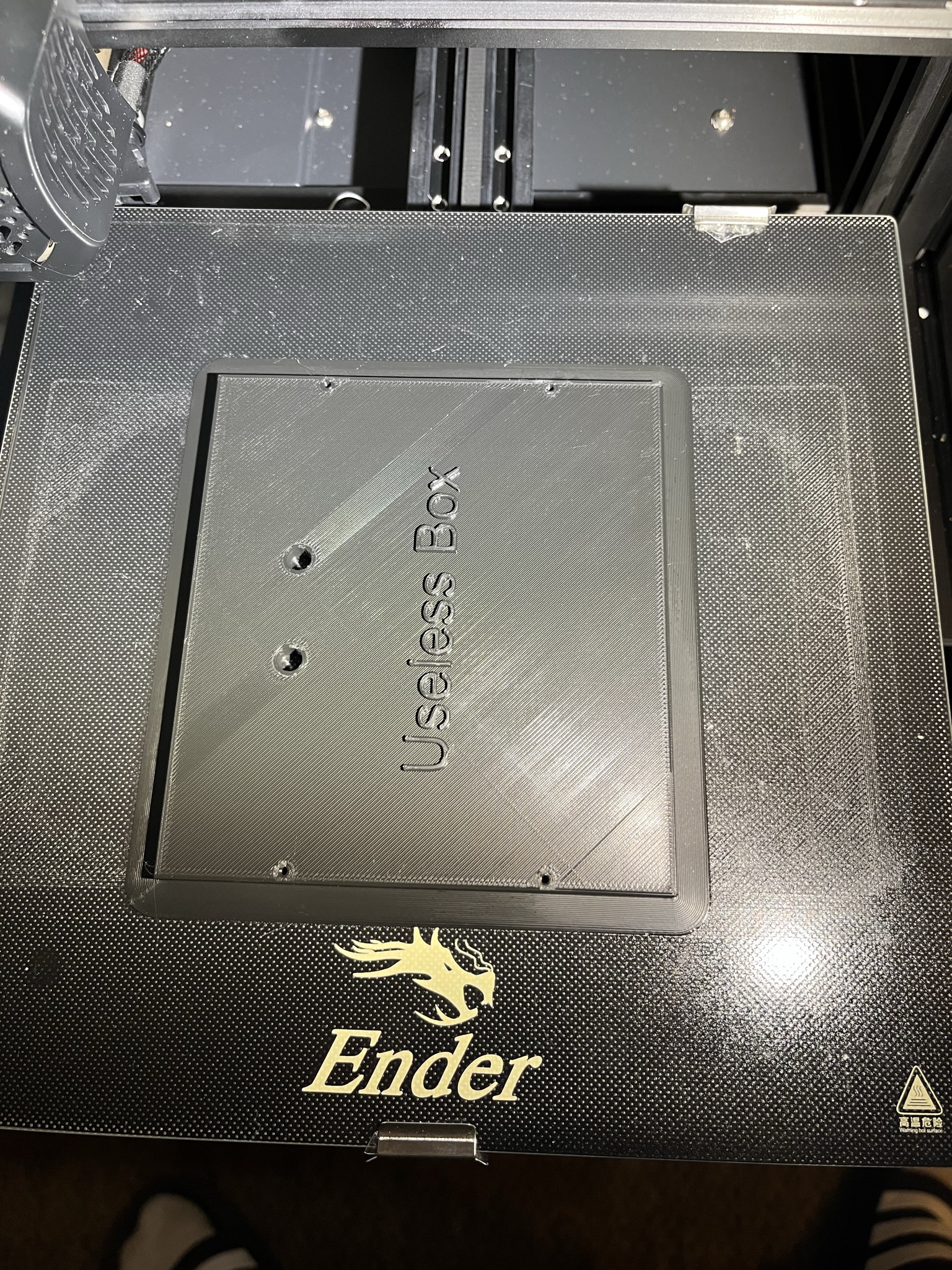
Box Bottom
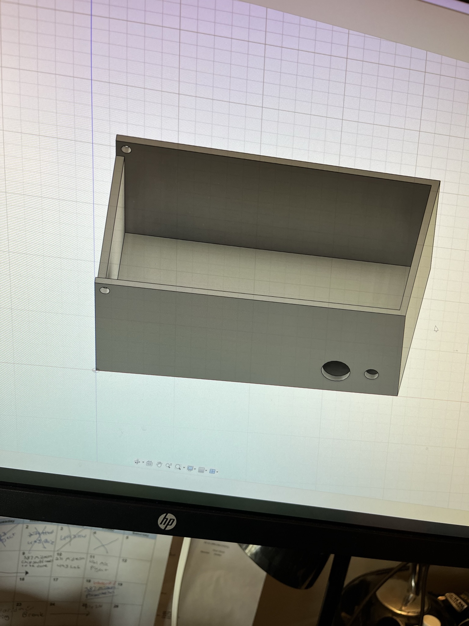
Box in Autodesk Fusion 360. I exported the drawing to Utilimaker Cura to “slice” it before it was printed.
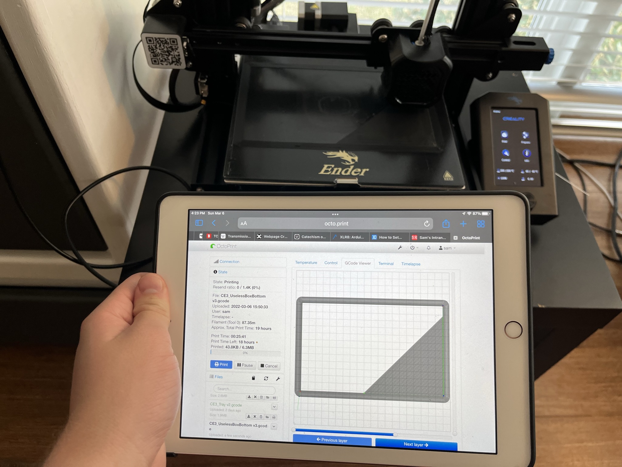
A raspberry pi running Octoprint is connected to my printer which provides a web interface to upload drawings and control the printer from. This printer is connected to the raspberry pi using a micro usb cable.
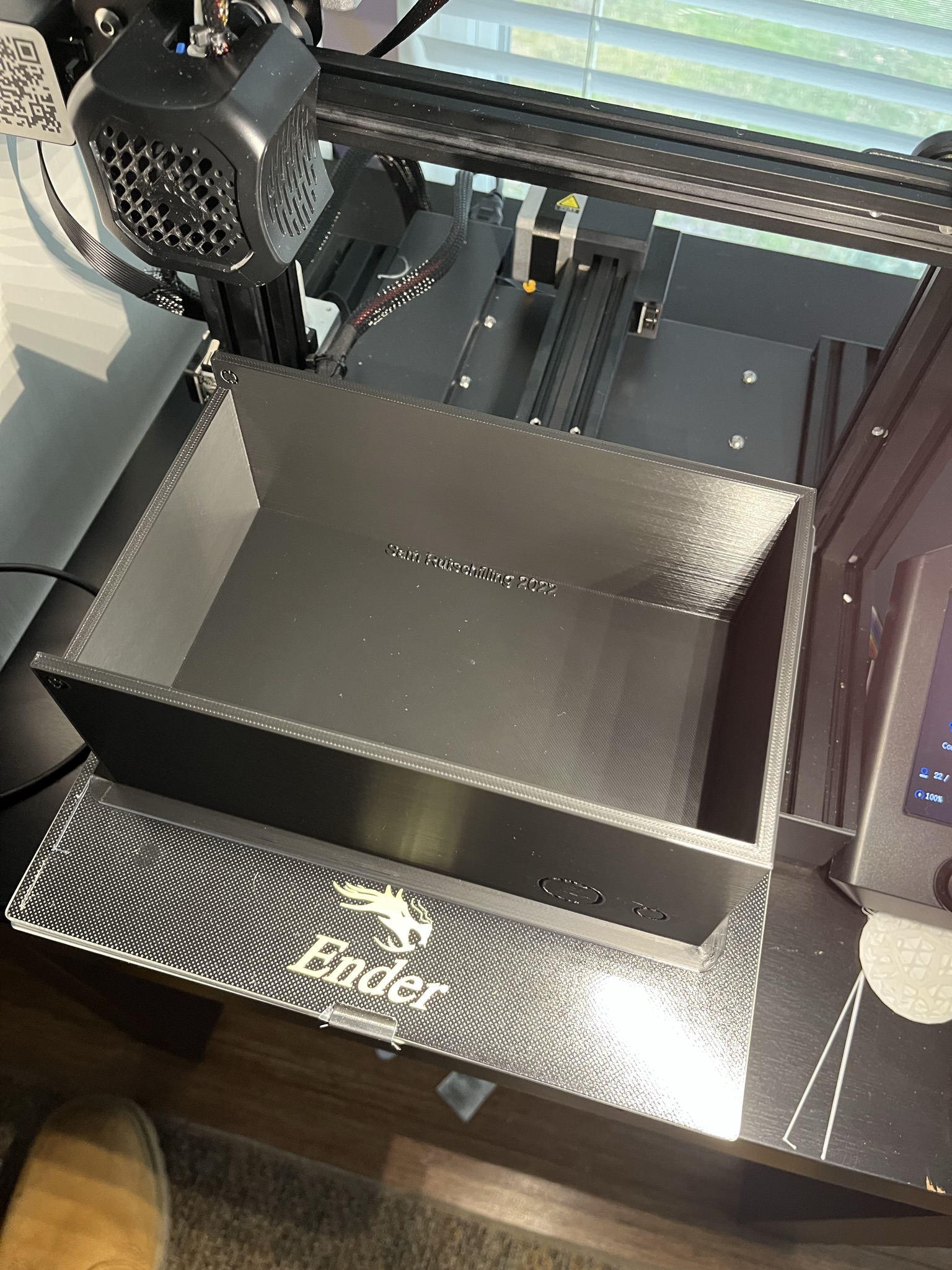
The bottom of the box used nearly the entire print volume of the printer, took approximately 22 hours to complete, and used approximately 200g ($4-5) of material.
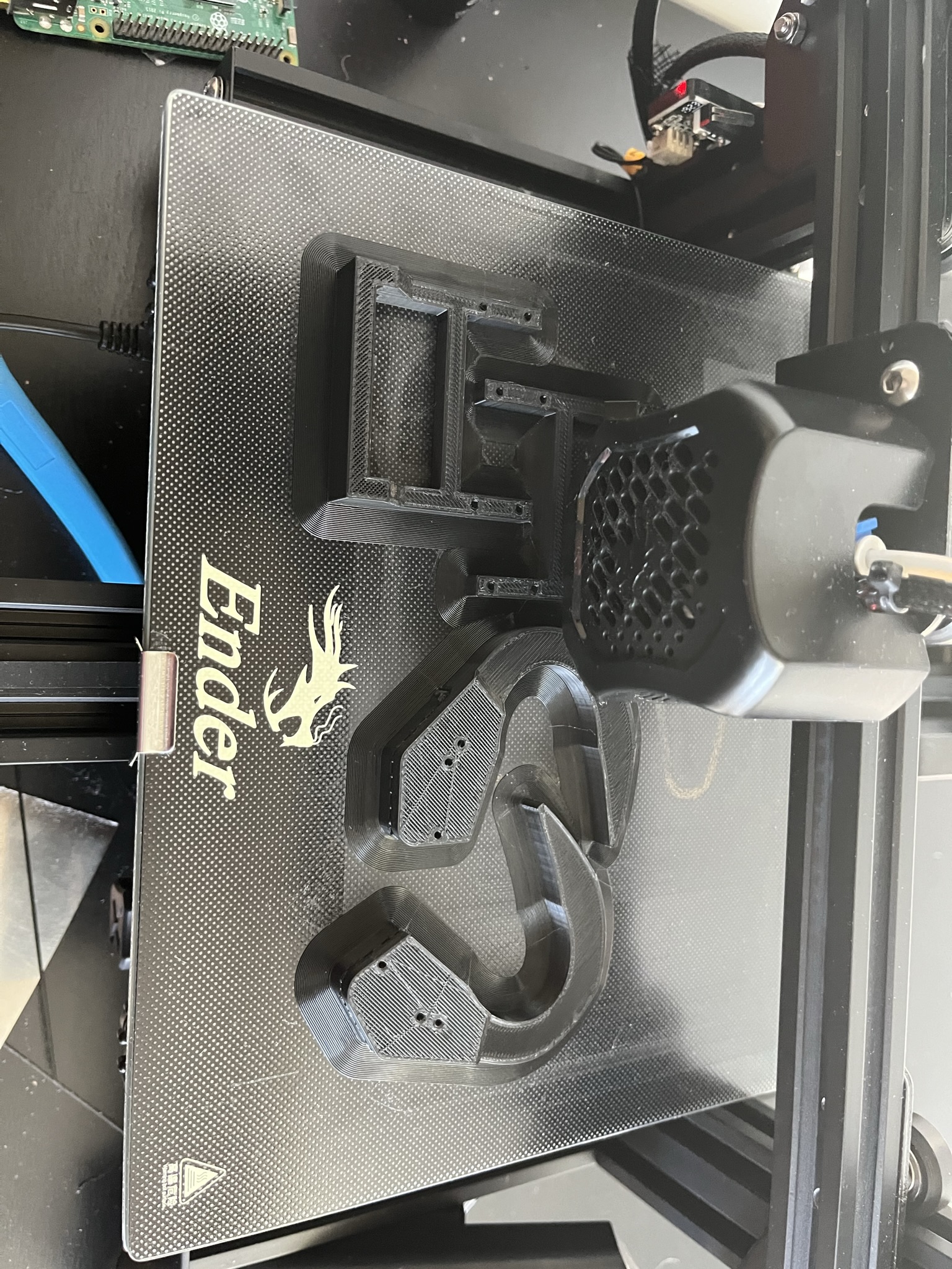
Box Top
The top of the Useless box, still on the printer. The larger holes are where the switches are mounted, and the smaller holes are screw holes.
Box Door
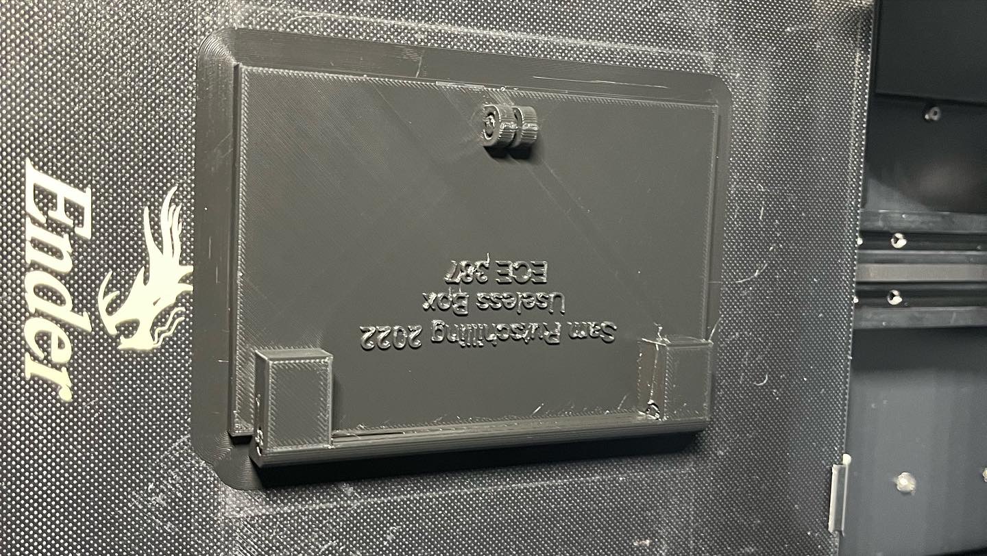
The box with hinge mounts on the printer. The raised area on the bottom was originally planned to be a rubber band mount to close the door, but this was not necessary as the door closes by itself.
Servo Arm
The brackets and arms also took some trial and error to get correct. The larger servo motors meant that the arms had to be offset to turn off the switches, as the box was not wide enough. This was the only real design change with the arm. I used screws to attach the arm to a mount that came with the servo. This just relies on friction between the gears to stay.
Assembly
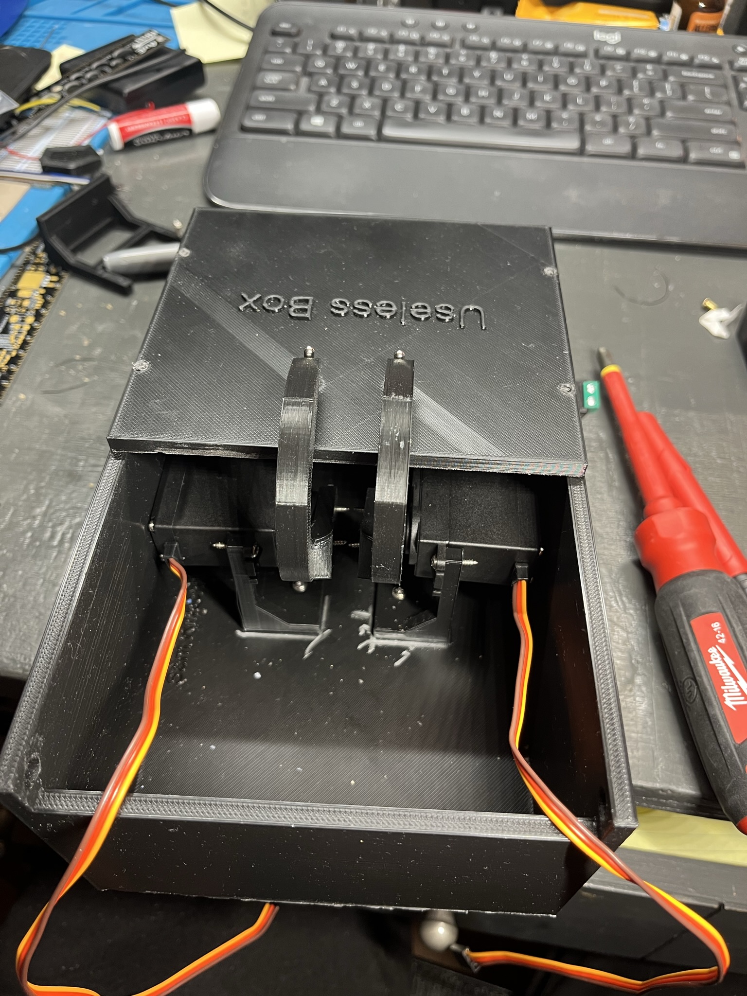
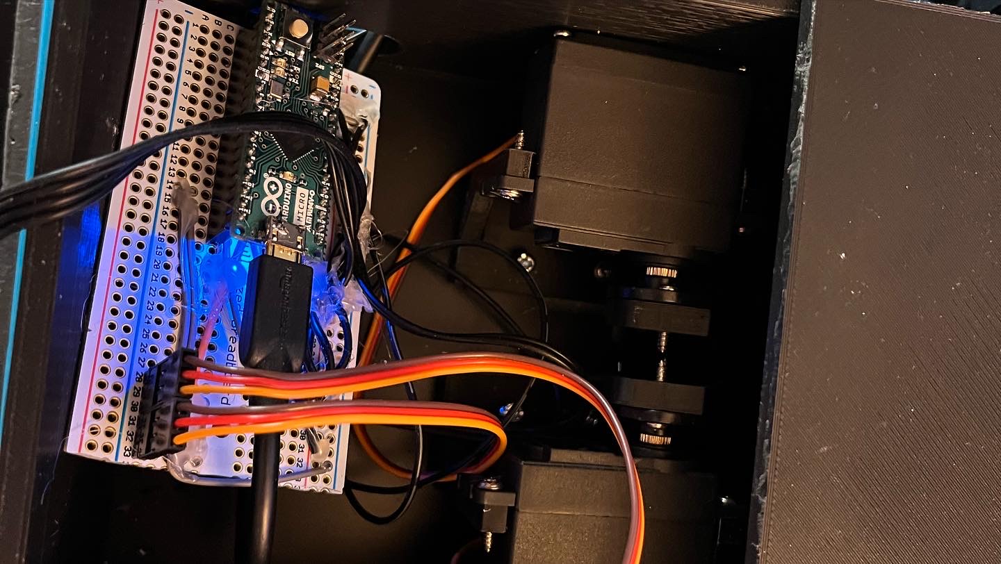
Servo Motors mounted inside The Box with switches and offset arms installed. From this view the width of the servo motors and box that required the arms to offset can be seen.
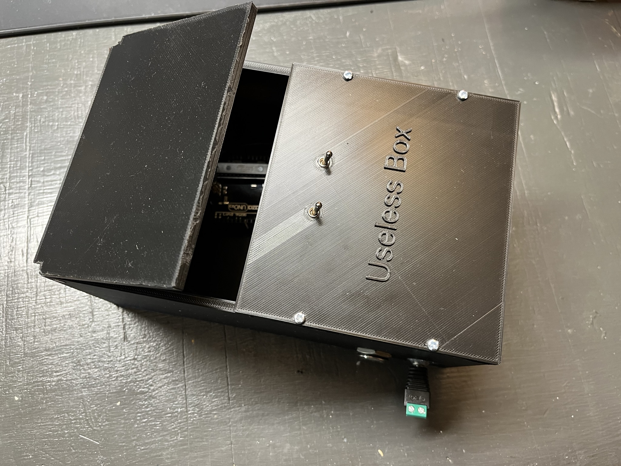
Assembled box with the door open.
Wiring and Connections
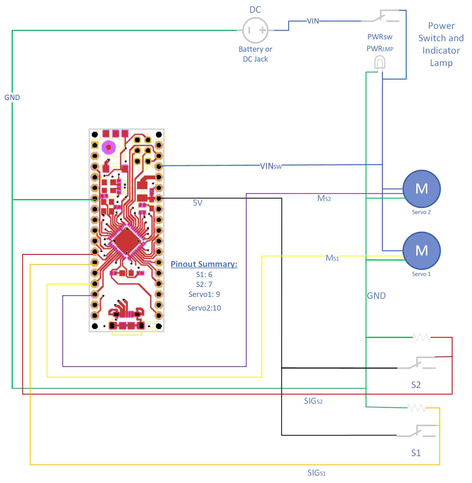 Above is the Schematic Diagram showing the connections for the Useless Box.
My Useless Box accepts a 5-7 V input on either the VIN jack on the outside of the box near the power switch, or the internal battery box which holds four AA batteries.
Internally, the servo motors are powered directly from the VIN port with no voltage regulation and this is why the input is limited to 7 volts. The Arduino Micro is then powered through its VIN pin. On the Arduino two digital input pins are used for the switches, and two PWM pins are used to control the servos. The wiring is very simple, with the only components being the servo motors, the switches, and bleed resistors for the switches.
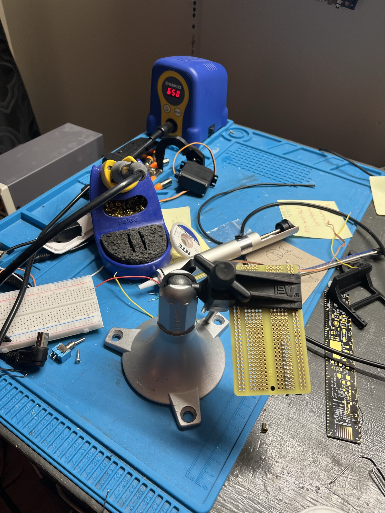
All of the connections are soldered or socketed to improve the reliability. I used a solder perfboard to attach all of the components and header pins for the Arduino and Servo motors.
The Servo headers are on the bottom left of the perfboard, while the black 4 wire cable goes to the switches mounted on the top of the box. After I soldered the components on to the perfboard I used hotglue on all connections to ensure the wires do not break off at their connections.
Issues
There were several issues and design changes while building the Useless Box. The first was my original choice for servo motor was very small 9g servo motors. After adding a large arm to be able to reach the switch, the motors did not have enough torque to turn the switches off. I than purchased some 20g replacement servos that are much larger and have much more torque. This required other design changes, however. Since the new motors were larger I had to redesign both the servo mounts and the servo arms. The mounts had to sit lower and be longer to fit the larger motor. The Servo arms had to have an offset so the arm would line up with a switch.
Another issue I experienced was with the Arduino. Originally I planned on using an Arduino Uno clone that I had been gifted several years ago. This has the same ATMEGA A328P on the official Arduino Uno, but as is common with the clones, does not have isolation between the USB power supply and board power supply. I found this out the hard way, by having power from my bench power supply applied through the VIN pin and USB power connected for programming. The ATMEGA microcontroller kept functioning but the USB controller failed and lost the ability to communicate. I then switched to a Arduino micro I had sitting around in preperation for a different project which fits much better inside the box but had its own challenges, such as the surface mounted micro USB programming port I managed to tear off the board almost immediately. Thankfully this was easily fixed with some solder and a few minutes of time. The real issue with the Arduino Micro came when it was time to program it in C. Those issues are explained in more detail in the C code section.
The final issue I had was following the input voltage requirements for the Servo motors. Since the servo motors are connected to the VIN connection and voltage is not regulated the voltage must stay within the servo’s voltage rating of 4.0-7.2V even though the Arduino is rated for higher voltage. Unfortunately, I did not follow this and connected the Useless box to a 12V power supply I have with the same barrel jack. This did not immediately cause a failure, but one of the servos did eventually fail (and let the smoke out). I replaced the servo with a spare and it has been functioning correctly (at the correct, 5V input) since.
Arduino Programming
The Arduino (C++) program I used for testing started with the Arduino example code for sweeping the servo motor. It is modified to move the servo motors based on the switch position. The code is located in the Arduino Folder. It uses two counters in the repeating loop part of the program to sweep each of the servos up when the switch was on, and then sweep it down when it was off. This required two for loops as since the servos are sitting opposite each other, they are rotating in the opposite direction. Also included in this code was code to check that the desired position for the Servos was not exceeding what it needed to in order to turn the switches off. This is important because occassionally the arm gets stuck without turning the switch off, especially if the user is being rough with it. If this motor would get stuck it would put a large amount of stress on the mechanical compoenents and servo motors while also having other unexpected behavior. The counter would count until it overflowed, and then the desired Servo position would become very negative, which also is not desired. The Arduino code also just uses the Arduino Servo library and the Servo.write() method to write the desired location to the servo.
C code
Although not required for this assignment I chose to challenge myself and implement the code in bare metal C code as well. I experienced two main challenges with this; programming the Arduino Micro Atmega A32U from AVRDUDE, since it operates differently then the A328P and implementing PWM on it, since the counters and registers are different then the A328P. The C code is located in the src folder. I used the same python script as the labs to compile and program the arduino, although some modifications to the settings for AVR-GCC and avrdude had to be made to accomidate the ATMEGA A32U.
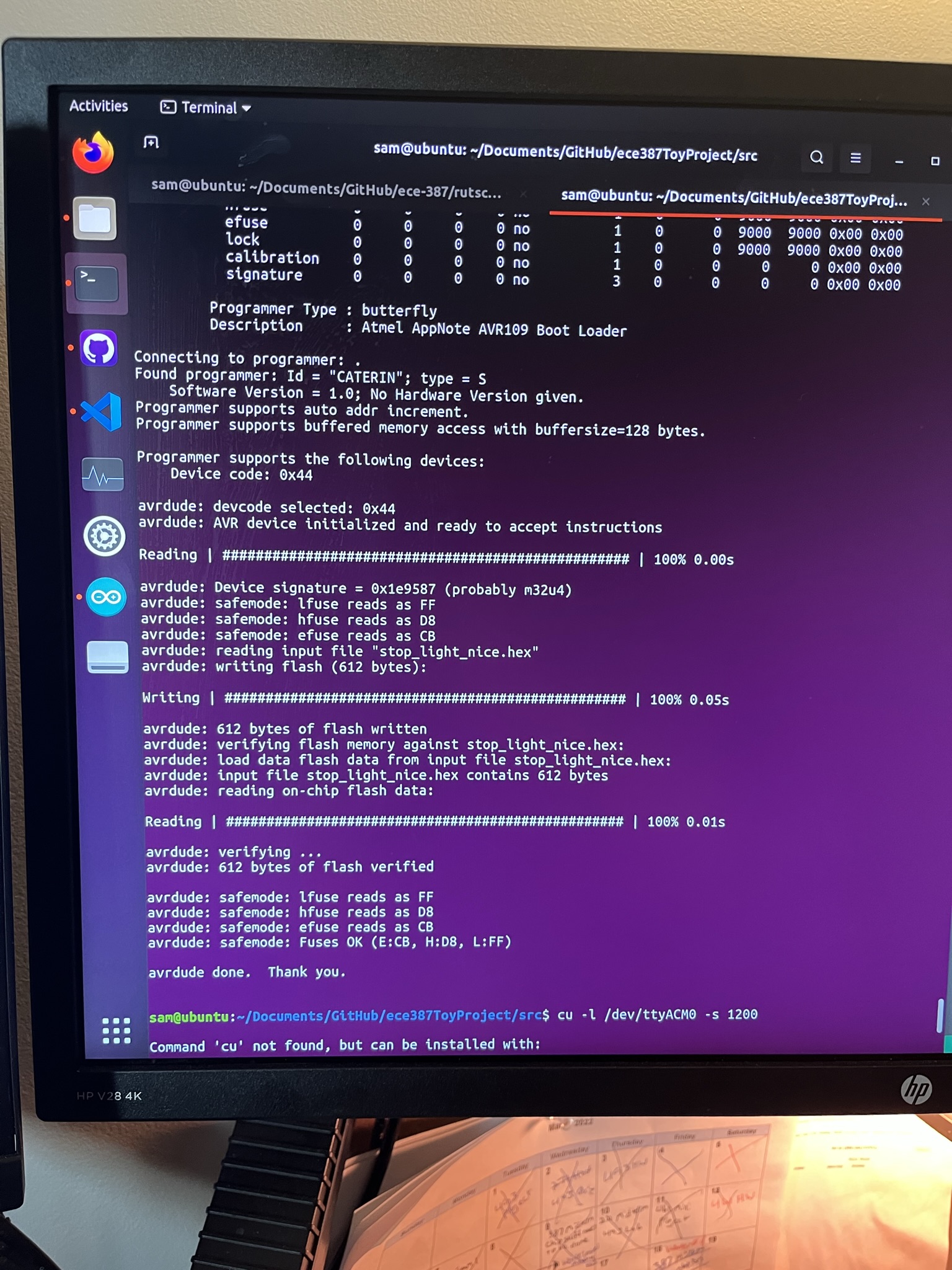
Programming the A32U from AVRDUDE initially proved to be a challenge but I was eventually able to figure out a procedure that was reliable. As with other labs, I started programming using AVRDUDE in an Ubuntu Virtual machine with the Arduino connection passed through from my Windows laptop. This was unreliable because of the procedure for programming, so eventually I decided to program the Arduino solely from a spare laptop I have that runs Ubuntu natively.
The Arduino Micro’s Atmega A32U microcontroller requires a very specific set of steps to be followed. The reset button must be pushed on the board (The Arduino IDE implements this somehow in software, but I was unable to). Then there are 8 seconds to do the remaining steps: The serial port the Arduino is attatched to must be opened at a rate of 1200bps and then immediately closed. I accomplished this by using the serial monitor in the Arduino IDE. Then finally the script that compiles and programs the Arduino using avr-gcc and AVRDUDE must be run. This procedure on the native linux machine had a very high success rate.
The second large issue with programming in C was implementing PWM on the A32U in the Arduino Micro. The registers and counters used for PWM on the A32U are different than those used in the Atmega A328P we used in the labs. I first tried to set up PWM the same was using the different counter configuration for the A32U but this proved time consuming and did not work. I was Thankfully able to find help Online where others had implemented PWM on the Atmega A32U.
With those two issues solved, the rest of the C code is essentially ported from the Arduino Code version. The only differences are syntax and the obvious lack of the Servo.write() method. The C-Code version of the code is what is used for the demonstration video.
Power Reduction Techniques:
As this project can be battery powered, power reduction techniques are necessary to ensure a long battery life. The useless box can be powered by 4AA batteries in a battery case that is under the useless box door. The box’s ATMEGA A32U microcontroller - integrated into the Arduino Micro, is programmed using baremetal C in order to reduce the overhead and power consumption. This also uses direct manipulation of counters for PWM control so any overhead required by the Arduino libraries was eliminated. The battery life is still quite poor however, as the Servo motors can draw approximately 1 amp each under load. When operating under battery power, the AA batteries cannot output 2A for a long period of time, so battery life is poor.
Improvements:
As with any project, by the time it was finished there were several things that I would do differently if I were to do the project again. One of these changes would be further improving the power consumption. Even with the power reduction techniques described above the power consumption and battery life are still rather poor. One easy power reduction technique I would employ if starting again is controlling the power to the servo motors using a MOSFET, so they would only have power when they are active and have a reason to be moving. Another power reduction technique I would have employed is using interrupts for the switch control, so the microcontroller could be in a ultra low power state when niether of the servos are moving. Finally instead of using the Arduino micro with the ATMEGA 32U microcontroller, I likely would use a bare ATMEGA A328P for the better packaging and power consumption.
Other power improvments for the box could include a rechargable battery system. A rechargable lithium battery could be implemented into the system power it for longer periods of time. This also could be implemented with a USB power source to easier find a power source versus the DC barrel jack on the current Useless Box. As a sidenote, the barrel jack is necessary without a permanant onboard battery due to the high power requirements of the servos that a USB power supply (especially a computer) cannot support.
Mechanical improvements I would make if I were starting again would be to design the bottom of the box with the servo mounts intergrated. This would increase the servo mounts structual integrity, would reduce their movement, and remove the need for the hot glue I added to keep the motors from moving. I also would use screws to mount the servo “arms” to the servo motors instead of relying on friction of the gears to work. While designing the initial bottom of the box I should have also considered the motion of the door opening so that I would not have had to knotch the door on the sides to let it open. This was the first project I had completed with 3-D printed parts and Fusion 360, so it was a learning expierence both with the 3-D design software and my 3-D printer.
Cost
Cost breakdown. Costs for 3D printed parts are estimated from the slicer’s estimate of the filament required for printing.
| Part | Quantity | Cost | Note |
|---|---|---|---|
| Box Bottom | 1 | $5.74 | PLA |
| Box Top | 1 | $1.10 | PLA |
| Box Door | 1 | $1.02 | PLA |
| Servo Arms | 2 | $0.55 | PLA |
| Servo Mounts | 2 | $0.55 | PLA |
| Original Servos | 2 | $10.99 | |
| Larger Servos | 2 | $22.35 | |
| Switches | 2 | $1.60 | |
| Arduino Micro | 1 | $21.00 | |
| Perfboard | 1 | $6.99 | Adafruit |
| Hinge Rod | 1 | $8.51 | |
| Miscelaneous | N/A | $5 | Other Various Parts |
Total: $85.40
More Information:
Additional Documentation found at: https://srutschilling.net/ECE387/ToyProject/
Additional help with PWM on ATMEGA 32U from this link.